Ray Valley
Aquatic Biologist and BioBase Product Expert
BioBase’s EcoSound is a powerful cloud platform for creating high definition lake or coastal maps of depth, aquatic vegetation (or seagrass), and bottom hardness from Lowrance® and Simrad®
sonar systems. For the user, the process of converting volumes of raw sonar and gps signals into an intuitive map is easy and requires very little input upfront. Record your sonar while out on the water to a microSD card, plug the card into your PC back at the office, log into your BioBase account and upload. Algorithms on remote servers do the rest of the work. However, one of the most frequently overlooked parts of this equation is careful attention to the proper installation of the transducer sensor that is pinging the bottom and collecting all the information below the boat. The importance of proper transducer installation cannot be overstated. If the transducer is not properly placed on the boat or not at the appropriate angle, your BioBase outputs could be inaccurate. Researchers and Data Analysts have heard it said many times (sometimes in more colorful language), the quality of the output depends on the quality of the input.
A common challenge…
Given all the unique boat hull designs, this issue is not unique to BioBase and anglers flood online message boards, social media groups, blogs, and YouTube to ask and learn about how to properly install their transducer in order to get the best picture of bottom so they can find and catch more fish. Almost all installation problems fall into 4 categories: Transducer is too low, too high, not angled correctly, or placed in a spot on the boat where interference with water flow is high. I’ll look a little closer at each of these issues. Before I go further, I should mention that the most common placement for transducers (for anglers, small craft boaters, and BioBasers) is on the transom of the boat, so examples below are focused on that placement.
Transducer is too low or too high
If the transducer is placed too low on the transom, significant turbulence will occur around the part of the mount that is below the boat hull. This will cause plumes of interference near the surface of the water, create “rooster tails” at high speeds, lose bottom lock, may cause false vegetation detects by EcoSound algorithms (Figure 1).

Transducer is not angled correctly
Sonar transducers emit a flashlight-like beam (traditional “broadband” sonar) or an elliptical copy scanner-like beam (Down- and Side-scan) while pinging. So, in the parlance of a flashlight, the angle you have that beam pointed affects what area is “lit up” and how strong the beam is. If it’s angled away from your target, obviously, the picture you see on the Sonar screen (and thus the mapping algorithms) will be affected (Figure 5).

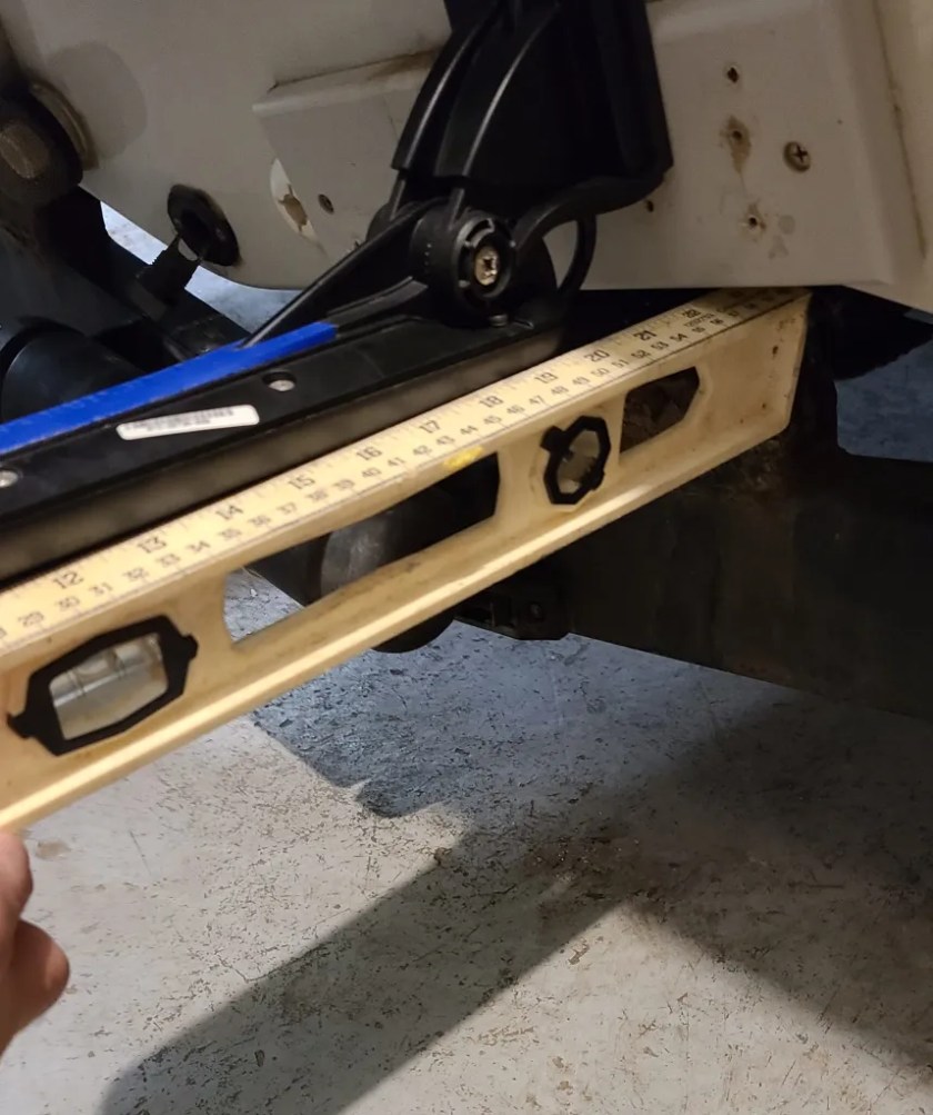
Use a torpedo level…and coins
Another commonly overlooked issue is that the angle that the boat sits loaded up with people and gear in the water may be different than how it sits on the trailer in the shop or garage. BUT, there’s a super easy way to account for that! Grab a handful of coins, a torpedo level and see below or watch this video.


Transducer placement on transom
Due to the huge range of hull sizes, designs, and motor mounts, this last issue is the most difficult one to be formulaic with a nice “do it this way” picture. If you can, try to mount the transducer no closer than 15″ from your lower unit. If you can, keep it out of the path of rivets, strakes, or any other feature of your hull that could interfere with the smooth, laminar flow of water. If you can, keep it away from bunks and straps. Lot’s of “if you can’s” and sometimes you can’t. Therefore, do your best, mount it up (again on a transducer mounting plate), and see how it goes. You will likely need to do some tweaks, but once you get it, you got it (Figure 8)! Lock it down! A properly mounted transducer should hold a bottom lock on most boats up to at least 40 knots. I am not a fan of portable transducers because there are too many points of failure and difficulty of getting it exactly the same each time you install it. Compared to the display, transducers are relatively inexpensive. If you need to outfit multiple survey boats but don’t have the budget for multiple displays, purchase multiple transducers, “permanently” install them and port your display to where its needed

Avoid side-scan interference
When you install your side-scan capable transducer envision the beam pattern of the schematic below in the location you would like to install your transducer. Will any of those beams hit an obstruction like the outboard lower unit or another transducer. Adjust the transducer so all beams can intercept the bottom unimpeded. Look for strange anomolies in the side scan image [shadows, suspended non-moving objects, different contrasts of colors on opposing sides despite a flat bottom (suggesting the transducer is tilted side-to-side)]

Additional video resources:
Demo of properly installed Lowrance TotalScan (also translates to more recent Active Imaging models)
Click Here for additional help with BioBase products.
Where can I buy the bracket?
Hi Rick – if you google “lowrance transducer bracket” you’ll find all sorts of options